Slit Gratings
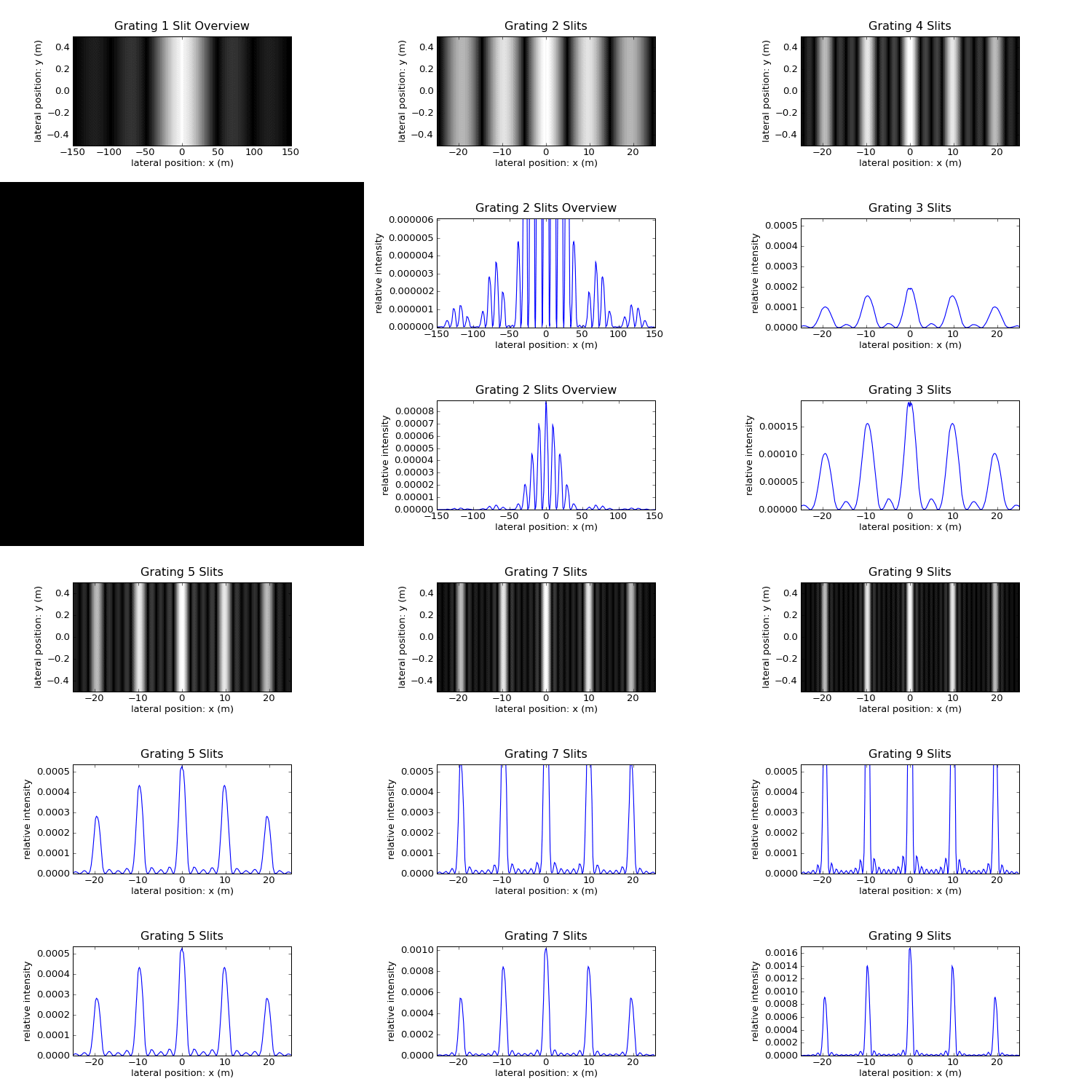
Various gratings in Fraunhofer diffraction regime.
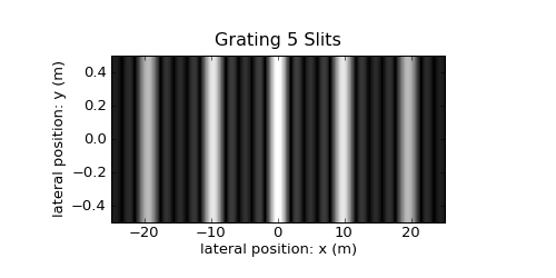
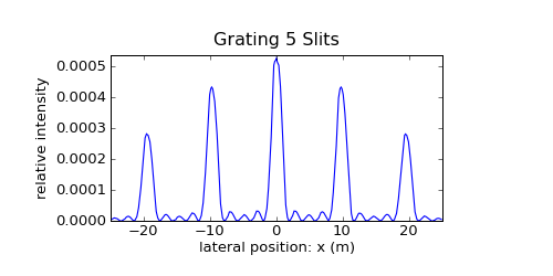
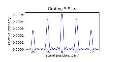
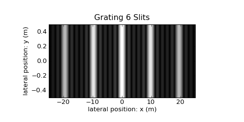
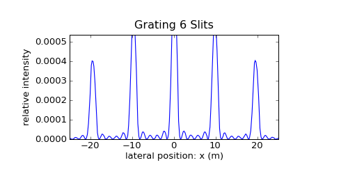
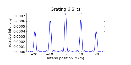
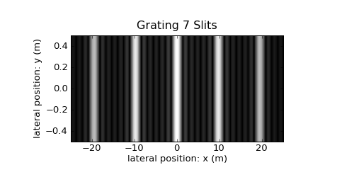
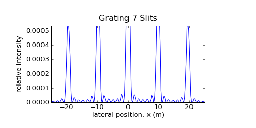
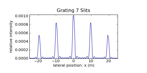
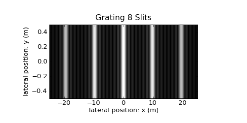
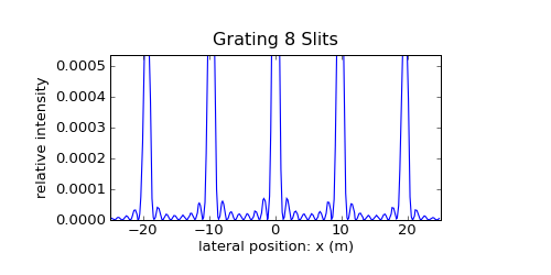
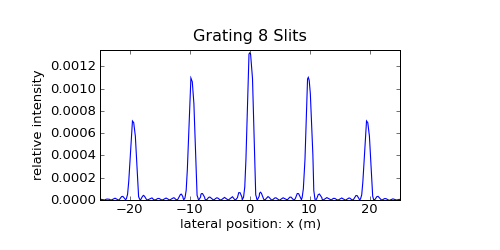
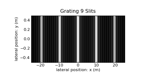
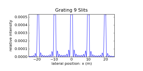
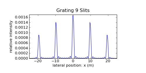
The slit number increases from one to nine. Top the intensity picture, middle and bottom 1D diagrams of the intensity.
The number of intermediate lobes between the main lobes increases with the slit number and is always equal to the slit number diminished by two. As the finite grating is the product of the infinite grating with a single broad slit, the Fraunhofer diffraction pattern is the convolution of the delta comb (multiplied by the form factor) with the sinc pattern of this single broad slit. With growing slit number the approximation of the delta comb, multiplied by the form factor, can be seen.
The first two pictures are overviews of the diffraction pattern of one or two slits. From then on the lateral \(x\) scale changes to fit only the central lobe of the form factor pattern.
Between the first and second picture and in the following sequence the intensity scale of the middle diagram never changes. The scale of the lower diagram in contrast is always fitting the whole profile.
The width of the broad mask slit is uncertain to one slit distance. From the Fourier space point of view, it is remarkable, that for all possible choices of the slit mask the convolution integral of this different sinc functions with the delta comb is always the same.
Overview of the Fraunhofer Diffraction Pattern of the Single Slit
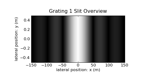
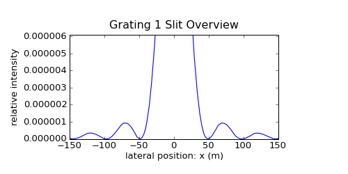
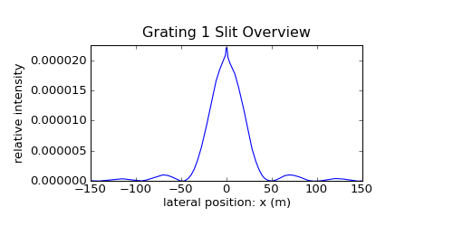
Overview of the Fraunhofer diffraction pattern of the single slit, taken at quasi-infinity at large \(z\).
In the bottom diagram, a limitation of the used algorithm's applicability becomes visible in the innermost peak region.
The intensity diffraction pattern is the square of the sinc function.
Overview of the Diffraction Pattern of the Double Slit
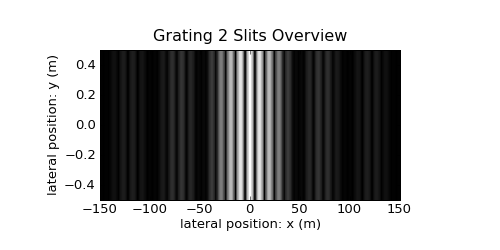
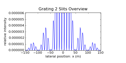
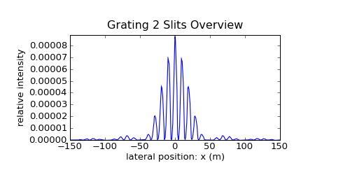
When two slits are combined, their amplitudes interfer.
The aperture consisting of two parallel slits can be constructed by convolving the single slit aperture with a two delta peak distribution. Thus, the Fraunhofer diffraction pattern is the product of the two diffraction patterns arising from each convolution component. The factor resulting from the single slit is now called the form factor, which is multiplied onto the higher-frequency diffraction amplitude resulting from the double delta peak.
The Fourier transform diffraction amplitude of the double delta peak is an infinite cosine. Thus, the intensity form factor of the squared sinc function is multiplied by the squared cosine to result in the final diffraction intensity pattern visible in the diagrams.
For more slits, the form factor will in the following pictures stay always the same, as the width of the single slits incorporated is unaltered. Therefore we will focus on the central lobe of the form factor, where the real action takes place between the narrow lobes of the fine pattern. For more than one slit, the aperure is again a convolution with a multi-delta distribution, and the pattern created by them will be visible as the modulation pattern.
Gratings
2 Slits
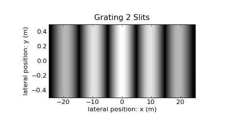
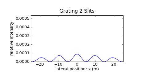
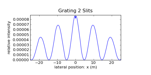
The central lobe of the form factor envelope from the single slit with the cosine square modulation from the double slit.
The \(x\) scale has been magnified as discernable from the numbers. The intensity scale in the middle diagram has been switched. Nothing else is changed with respect to the previous configuration.
3 Slits
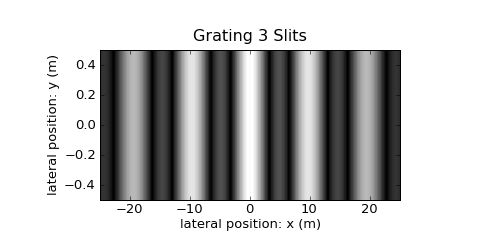
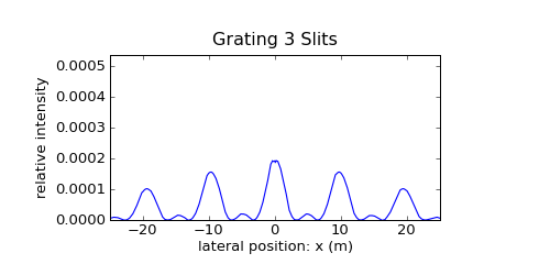
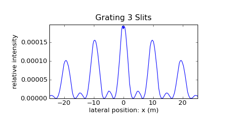
As is visible in the three diagrams, the pattern exhibits now the following features:
- Two roots between each two main lobes, forming the boundaries for an additional minor lobe between the main lobes.
- The minor lobes appear at the positions of the roots for two slits alone.
- The intensity of the minor lobes is much attenuated with respect to the main lobes.
- The main lobes are amplified and more pronounced with respect to the configuration with only two slits (see middle diagrams).
4 Slits
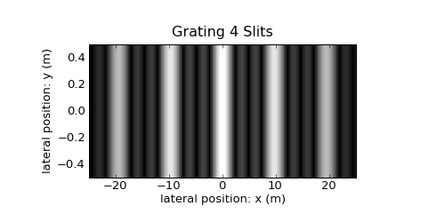
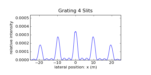
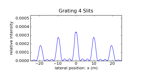
Now there are two minor lobes.
5 Slits
6 Slits
7 Slits
8 Slits
9 Slits
Summary
From comparing the different configurations using the middle (absolute) diagrams, the following features can be discerned:
- The peak intensity of the main peaks increases supralinearly with slit number.
- The peak intensity of the outer minor lobes increases with slit number, but sublinearly. The intensity of the inner minor lobes drops.
From the lower (relative) diagrams, the following can be seen:
- The relative intensity of the minor lobes drops with increasing slit number.
- The sharpness (the inverse width) of the main peaks increases with slit number.
For infinitely many slits, the diffraction pattern will resemble a delta comb, delta distributions in perfect array, except for the form factor, without any side lobes. As infinity cannot be reached, minor lobes will always gain some intensity.